

Can Sterling Power Inverters Be Repaired

In this post we will try to learn how to diagnose and repair an inverter, past comprehensively learning the various stages of an inverter, and how a basic inverter functions.
Before we discuss how to repair an inverter it would be of import for you to first get fully informed regarding the basic functioning of an inverter and its stages. The following content explains regarding the important aspects of an inverter.
Stages of an Inverter
Every bit the name suggests DC to Ac inverter is an electronic device which is able to "capsize" a DC potential normally derived from a lead-acid battery into a stepped-up AC potential. The output from an inverter are normally quite comparable to the voltage that is establish in our domestic AC Mains outlets.
Repairing sophisticated inverters are not easy due to their many involved circuitous stages and requires expertise in the field. Inverters which provide sine wave outputs or the ones which use PWM technology to generate modified sine wave tin exist difficult to diagnose and troubleshoot for the folks who are relatively new to electronics.
However, simpler inverter designs that involve basic operating principles can be repaired even by a person who is not specifically an expert with electronics.
Earlier we move into the error finding details it would be important to discuss how does an inverter work and the dissimilar stages unremarkably an inverter may incorporate:
An inverter in its most basic form may be divided into iii key stages viz. oscillator, driver and the transformer output stage.
Oscillator:
This phase is basically responsible for the generation of oscillating pulses either through an IC circuit or a transistorized circuit.
These oscillations are basically the productions of alternating battery positive and negative (ground) voltage peaks with a particular specified frequency (number of positive peaks per second.) Such oscillations are generally in the grade of square pillars and are termed as square waves, and the inverters operating with such oscillators are called foursquare wave inverters.
The in a higher place generated square wave pulses though are too weak and can never be utilized to drive high current output transformers. Therefore these pulses are fed to the next amplifier stage for the required task.
For info on Inverter oscillators you can also refer to the complete tutorial which explains how to design an Inverter from the scratch
Booster or Amplifier (Driver):
Here the received oscillating frequency is suitably amplified to high current levels using either power transistors or Mosfets.
Though the boosted response is an AC, it is still at the battery supply voltage level and therefore cannot be used to operate electrical appliances which work at higher voltage AC potentials.
The amplified voltage is therefore finally applied to the output transformer secondary winding.
Output Power Transformer:
Nosotros all know how a transformer works; in Air-conditioning/DC ability supplies information technology is commonly used to step-down the applied input mains AC to the lower specified AC levels through magnetic induction of its ii windings.
In inverters a transformer is used for similar purpose only with just opposite orientation, i.e. here the low level AC from the to a higher place discussed electronic stages is applied to the secondary windings resulting in an induced stepped up voltage across the main winding of the transformer.
This voltage is finally utilized for powering the various household electrical gadgets like lights, fans, mixers, soldering irons etc.
Basic Principle of Operation of an Inverter
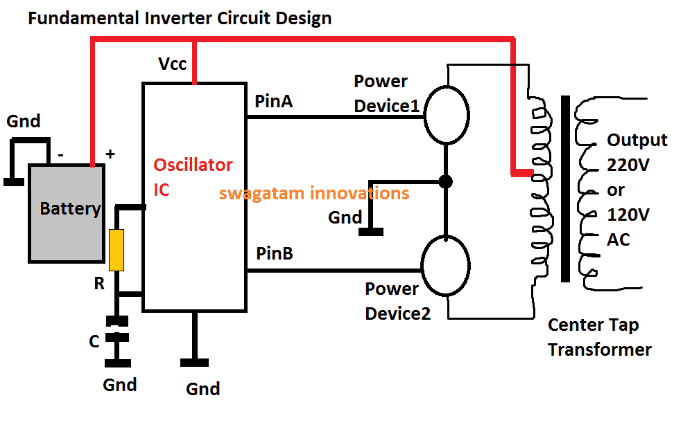
The above diagram shows the well-nigh fundamental design of an inverter, the working principle becomes the back bone for all conventional inverter designs, from the simplest to the nearly sophisticated ones.
The functioning of the shown blueprint may be understood from the following points:
1) The positive from the battery powers the oscillator IC (Vcc pin), and also the center tap of the transformer.
2) The oscillator IC when powered starts producing alternately switching Hi/lo pulses across its output pins PinA and PinB, at some given frequency charge per unit, mostly at 50Hz, or 60Hz depending as per the state specs.
three) These pinouts can be seen continued with the relevant power devices #1, and #2, which could be mosfets or power BJTs.
3) At any instant when PinA is loftier, and PinB is depression, the Ability Device#1 is in the conducting mode, while Power Device#two is held switched OFF.
iv) This state of affairs connects the upper tap of the transformer to ground via the power device#1, which in turn causes the battery positive to pass through upper half of the transformer, energizing this section of the transformer.
five) Identically, in the next instant when the pinB is high and PinA is depression, the lower primary winding of the transformer becomes activated.
half dozen) This cycle repeats continuously causing a push-pull loftier current conduction beyond the 2 halves of the transformer winding.
7) The above activity within the transformer secondary causes an equivalent amount of voltage and current to switch across the secondary by means of magnetic induction, resulting in the product of the required 220V or the 120V AC across the secondary winding of the transformer, as indicated in the diagram.
DC to Ac Inverter, Repairing Tips
In the above explanation a couple of things become very critical for obtaining correct results from an inverter.
1) First, the generation of the oscillations, due to which the power MOSFETs are switched ON/OFF, initiating the process of electromagnetic voltage induction across the main/secondary winding of the transformer. Since the MOSFETs switch the main of the transformer in a button-pull manner, this induces an alternating 220V or 120V AC across the secondary of the transformer.
2) The 2d important factor is the frequency of the oscillations, which is fixed equally per the state'due south specifications, for case countries that supply 230 V, generally accept a working frequency of 50 Hz, in other countries where 120 V is specified mostly work at sixty Hz frequency.
three) Sophisticated electronic gadgets similar Idiot box sets, DVD players, computers etc. are never recommended to be operated with square wave inverters. The sharp rise and autumn of the square waves are just not suitable for such applications.
four) Notwithstanding at that place are ways through more complex electronic circuits for modifying the square waves and then that they get more than favorable with the in a higher place discussed electronic equipment.
Inverters using farther complex circuits are able to produce waveforms almost identical to the waveforms bachelor at our domestic mains Air conditioning outlets.
How to Repair an Inverter
In one case you get well versed with the different stages normally incorporated in an inverter unit as explained above, troubleshooting becomes relatively piece of cake. The following tips volition illustrate how to repair DC to AC inverter:
Inverter is "Expressionless":
If your inverter is dead, practise preliminary investigations such as checking battery voltage and connections, checking for a blown fuse, lose connections etc. If all these are OK, open the inverter outer cover and exercise the following steps:
1) Locate the oscillator section; disconnect its output from its MOSFET stage and using a frequency meter confirm whether or not it is generating the required frequency. Normally, for a 220V inverter this frequency will be 50 Hz, and for 120V inverter this will be 60 Hz. If your meter reads no frequency or a stable DC, it may betoken a possible error with this oscillator stage. Check its IC and the associated components for the remedy.
2) In case yous discover the oscillator phase working fine, become for the next stage i.e. the current amplifier stage (power MOSFET). Isolate the MOSFETS from the transformer and check each device using a digital multimeter. Recollect that y'all may have to completely remove the MOSFET or the BJT from the lath while testing them with your DMM. If you observe a particular device to be faulty, replace it with a new one, and check the response past switching ON the inverter. Preferably connect a high wattage DC bulb in serial with the battery while testing the response, just to be on the safer side and prevent any undue harm to the battery
iii) Occasionally, transformers tin can also become the major cause for a malfunction. Y'all can check for an open winding or a loose internal connectedness in the associated transformer. If you lot find it to be suspicious, immediately change it with a new one.
Although it won't be that easy to learn everything most how to repair DC to AC inverter from this chapter itself, but definitely things volition start "cooking" equally y'all delve into the procedure through relentless practise, and some trial and error.
Still accept doubts...feel gratuitous to postal service your specific questions here.

Source: https://www.homemade-circuits.com/how-inverter-functions-how-to-repair/
Posted by: yatescoultan.blogspot.com
0 Response to "Can Sterling Power Inverters Be Repaired"
Post a Comment